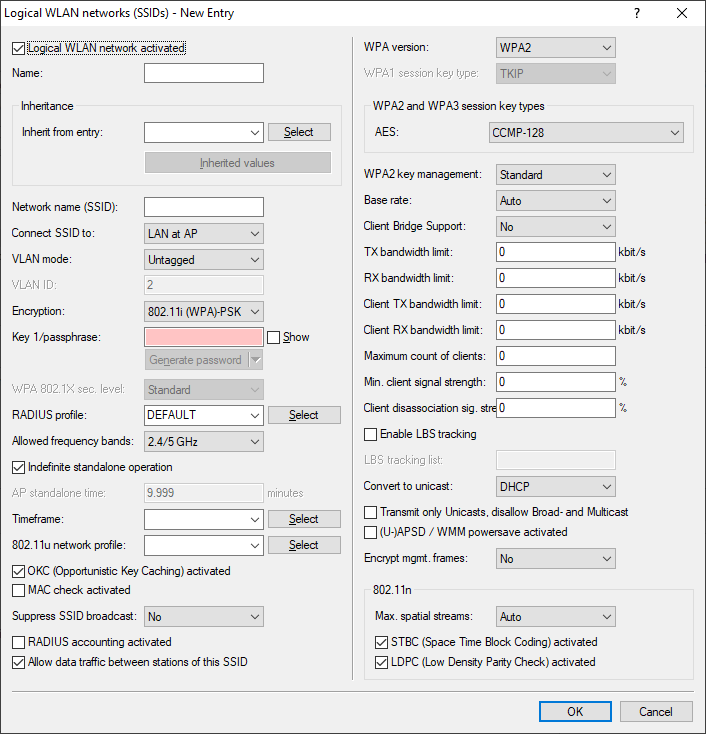
Under you set the logical WLAN network parameters that the WLC assigns to the APs. The following parameters can be defined for each logical WLAN network:
- Logical WLAN network activated
- Enable the logical WLAN network by clicking on this option.
- Name
- Here, specify a name which uniquely identifies the logical WLAN network.
- Inheritance
- If you wish to create entries that differ only slightly from existing ones, you can choose a "parent" entry here and select the parameters which are to be applied each time it is used.
Important: A "parent" entry itself can contain inherited entries. Try to ensure that the structure of inherited entries is not too complex, otherwise they may be difficult to understand and configure.
- Network name (SSID)
- Enter the SSID of the WLAN network here. All stations that belong to this WLAN network must use the same SSID.
- SSID connect to
- Here you select which of the AP's logical interfaces is to be associated with the SSID, i.e. where the AP sends the data packets for this SSID.
- "LAN": The AP forwards the data packets locally into the LAN (LAN-1) by default. It must be configured appropriately to do this.
- "WLC-Tunnel-x": The SSID is connected to a WLC bridge layer-3 tunnel. The AP sends all data packets to this tunnel and thus to the WLC. This tunnel must be configured on the WLC.
- "L2TP-ETHERNET-x": The SSID is connected to an L2TPv3-Ethernet tunnel. This enables the automatic break-out of WLAN SSIDs through L2TP-Ethernet tunnels. General information on the topic of L2TPv3 is available in the section Layer-2 tunneling protocol (L2TP). L2TPv3 tunnels are recommended as an alternative to the classic WLC layer-3 tunnel if the latter limits the WLAN throughput. Higher maximum throughputs can be achieved with L2TPv3. Then adjust the usage of the L2TP-ETHERNET-x interface used on the WLC, e.g. for further use on the IP router or LAN bridge. Note: Both the WLC and the managed access points must support LCOS 10.50 or higher.
Note: Note that although forwarding all data packets to the WLC allows you to define routes and filters centrally, this creates a heavy load on the WLC. This model demands a correspondingly high bandwidth in order to transfer all of the data traffic of this and any other SSIDs that are connected to this WLC via WLC tunnel. - VLAN mode
- This item sets the AP VLAN mode for packets belonging to this WLAN network (SSID). VLAN IDs are used if the VLAN module is enabled in the physical WLAN parameters of the AP. Otherwise the AP ignores all VLAN settings in the logical networks. Even with VLAN activated, it is possible to operate the network untagged.
- "Untagged": The AP does not tag data packets from this SSID with a VLAN ID.Note: Even with VLAN activated, it is possible to operate a WLAN network untagged. The VLAN ID '1' is reserved internally for this.
- "Tagged": The AP marks the data packets with the VLAN ID specified as follows.
- "Untagged": The AP does not tag data packets from this SSID with a VLAN ID.
- VLAN-ID
- VLAN ID for this logical WLAN network
Note: Please note that to use VLAN IDs in a logical WLAN network, you must set up a management VLAN ID (see physical WLAN parameters).
- Encryption
- This item sets the encryption method or, in the case of WEP, the key length for packet encryption in this WLAN.
- Key 1 / passphrase
- You can enter the key or passphrase as an ASCII character string. An option for WEP is to enter a hexadecimal number by adding a leading "0x". The following character string lengths result for the formats used:
- WPA-PSK: 8 to 63 ASCII characters
- WEP128 (104 bit): 13 ASCII or 26 hex characters
- WEP64 (40 bit): 5 ASCII or 10 hex characters
- RADIUS profile
- Specify which RADIUS profile the AP should receive for this network, so that it can connect directly to the RADIUS server if necessary. Leave this field blank if the WLC is to handle RADIUS requests.
Note: You configure the RADIUS profiles in the corresponding table.
- Allowed frequency bands
- Here you set the frequency band used by network participants for transmitting data on the wireless network. You can select the 2.4-GHz band, the 5-GHz band, or both bands. In addition, the 6 GHz band is available.
- Indefinite standalone operation
- If the standalone operation for the WLC is configured so that the WLAN networks are broadcast indefinitely (value: 9999), this applies to networks with local break-out on the LAN as well as to networks connected via WLC tunnel. If the WLC fails, both types of network will continue to be broadcast: However, this only makes sense for local break-out networks on the LAN, since networks connected via the WLC tunnel have lost their end point (the WLC) and are therefore out of operation.
This option allows the two types of networks to be treated separately.
- With this option enabled, local break-out networks will indefinitely operate standalone. In contrast, networks that break-out via a WLC tunnel are only broadcast if the WLC can be reached.
- Without this option enabled, the time specified under AP standalone time applies.
- AP standalone time
- The time in minutes that a managed-mode AP continues to operate in its current configuration.
The configuration is provided to the AP by the WLC and is optionally stored in flash memory (in an area that is not accessible to LANconfig or other tools). Should the connection to the WLC be interrupted, the AP will continue to operate with the configuration stored in flash for the time period entered here. The AP can also continue to work with this flash configuration after a local power outage.
If there is no connection to the WLC after this time period has expired then the flash configuration is deleted and the AP goes out of operation. As soon as the WLC can be reached again, the WLC transmits the configuration to the AP again.
This represents an effective measure against theft as the AP deletes all security-related configuration parameters after this time has expired.
Important: If the AP establishes a backup connection to a secondary WLC then the countdown to the expiry of standalone operation stops. The AP and its WLAN networks remain active as long as there is a connection to a WLC.Important: Please note that the AP only deletes the configuration in flash memory after the time for standalone operation has expired, and not when the power is lost!
- Timeframe
- Select one of the time frames defined in . This can be used to restrict the broadcast of this SSID to the times defined there. This can be used, for example to activate a WLAN in a school only during class times. The time frame for the WLAN controller is configured in the same way as the settings in Timeframe.
- 802.11u network profile
- Select the Hotspot 2.0 profile from the list.
- OKC activated
- This option enables the opportunistic key caching. OKC makes it easy for WLAN clients to quickly and conveniently roam between WLAN cells in wireless environments with WPA2-Enterprise encryption.
- MAC check activated
- The MAC addresses of the clients that are allowed to associate with an AP are stored in the MAC filter list (). The MAC filter enabled switch allows you to switch off the use of the MAC filter list for individual logical networks.
- Suppress SSID broadcast
- You can operate your wireless LAN either in public or private mode. A wireless LAN in public mode can be contacted by any mobile station in the area. Your wireless LAN is put into private mode by activating the closed network function. In this operation mode, mobile stations that do not know the network name (SSID) are excluded from taking part in the wireless LAN.
With the closed-network mode activated, WLAN clients that use an empty SSID or the SSID "ANY" are prevented from associating with your network.
The option Suppress SSID broadcast provides the following settings:
- No: The AP publishes the SSID of the cell. When a client sends a probe request with an empty or incorrect SSID, the AP responds with the SSID of the radio cell (public WLAN).
- Yes: The AP does not publish the SSID of the cell. When a client sends a probe request with an empty SSID, the AP similarly responds with an empty SSID.
- Tightened: The AP does not publish the SSID of the cell. When a client sends a probe request with a blank or incorrect SSID, the AP does not respond.
Note: Simply suppressing the SSID broadcast does not provide adequate protection: When legitimate WLAN clients associate with the AP, this transmits the SSID in cleartext so that it is briefly visible to all clients in the WLAN network. - RADIUS accounting activated
- Select this option if you want to enable the RADIUS accounting in this logical WLAN network.
- Allow traffic between stations of this SSID
- Check this option if all stations logged on to this SSID may communicate with one another.
- WPA-Version
- Here you select which WPA version the AP is to offer to the WLAN clients for encryption.
- WPA1: WPA2 only
- WPA2: WPA2 only
- WPA3: WPA3 only
- WPA1/2: WPA1 and WPA2 in one SSID (radio cell)
- WPA2/3: WPA2 and WPA3 in one SSID (radio cell)
- WPA1/2/3: WPA1, WPA2 and WPA3 in one SSID (radio cell)
- WPA1 session key type
- If you use "802.11i (WPA)-PSK" for encryption, the method for generating a WPA1 session or group key can be selected here:
- AES: The AP uses the AES method.
- TKIP: The AP uses the TKIP method.
- AES/TKIP: The AP uses the AES method. If the client hardware does not support the AES method, the AP will change to the TKIP method.
- WPA2 and WPA3 session key types
- The method for generating the session or group key for WPA2 and WPA3 is selected here.
- Basis rate
- The defined basis rate should allow the slowest clients to connect to the WLAN even under poor reception conditions. A higher value should only be set here if all clients in this logical WLAN can be reached "faster". By setting the transmission rate to auto, the AP collects information about the transmission rates of the various WLAN clients. Clients automatically notify the AP of this rate with each unicast communication. The AP takes the lowest transmission rate from the list of associated clients and applies this to all multicast and broadcast transmissions.
- Client bridge support
- Enable this option for an AP if you have enabled the client-bridge support for a client station in WLAN client mode.
Note: Client-bridge mode is only available between two LANCOM devices.
- TX bandwidth limit
- With this setting, you define the overall bandwidth that is available for transmission within this SSID. A value of 0 disables the limit.
- RX bandwidth limit
- With this setting, you define the overall bandwidth that is available for reception within this SSID. A value of 0 disables the limit.
- Client TX bandwidth limit
- Here, you set the transmit-direction bandwidth limit (in kbps) available to each wireless client on this SSID. A value of 0 disables the limit.
- Client RX bandwidth limit
- Here, you set the receive-direction bandwidth limit (in kbps) available to each wireless client on this SSID. A value of 0 disables the limit.
- Maximum count of clients
- Here you set the maximum number of clients that may associate with this AP. Additional clients wanting to associate will be rejected by the AP.
- Min. client signal strength
- This value sets the threshold value in percent for the minimum signal strength for clients when logging on. If the client's signal strength is below this value, the AP stops sending probe responses and discards the client's requests. A client with poor signal strength will not detect the AP and cannot associate with it. This ensures that the client has an optimized list of available APs, as those offering only a weak connection at the client's current position are not listed.
- Client disassociation signal strength
-
If values drop below this threshold, the client is disassociated. This prevents the client from sticking with a WLAN connection that is actually unusable because of the poor signal rather than switching to a better cell phone connection—behavior that is all too common for mobile phones and can be very annoying for the user.
Important: This threshold only works if the value Minimum client signal strength is also set and the Client disassociation signal strength is less than this value.
- Enable LBS tracking
- This option specifies whether the LBS server is permitted to track the client information.
Note: This option configures the tracking of all clients in an SSID. In the Public Spot module you determine whether the LBS server is allowed to track the users who are logged on to the Public Spot.
- LBS tracking list
- With this entry, you set the list name for the LBS tracking. When a client successfully associates with this SSID, the AP transfers the specified list name, the MAC address of the client, and its own MAC address to the LBS server.
- Use long preamble for 802.11b
- Normally, the clients in 802.11b mode negotiate the length of the preamble with the AP. "Long preamble" should only be set when the clients require this setting to be fixed.
- (U)APSD / WMM Power Save activated
- Enable this option to signal stations that the power saving function (U)APSD ([Unscheduled] Automatic Power Save Delivery) is supported. (U)APSD is established in the 802.11e standard, and helps VoWLAN devices to increase their battery life. The related devices switch to power saving mode after login on a (U)APSD-capable AP. If the AP receives data packets for the related devices thereafter, it temporarily stores the data and waits until the VoWLAN device is available again. It then forwards the data. Afterwards, (U)APSD increases the latency time of the radio module, whereby it ultimately consumes less power. The individual rest periods may be so short that a VoWLAN device can still use the power saving function in the call state itself. However, the relevant devices must also support (U)APSD. WWM (Wi-Fi Multimedia) Power Save is a power saving function of the Wi-Fi Alliance and is based on U-APSD. Certain LANCOM APs are WMM® Power Save CERTIFIED by the Wi‑Fi Alliance.
- Max. spatial streams
- The spatial multiplexing function allows the AP to transmit multiple data streams over separate antennas in order to increase the data throughput. The use of this function is only recommended when the remote device can process the data streams with corresponding antennas.
Note: In the 'Auto' setting, the AP uses all of the spatial streams supported by this WLAN module.
- Allow short guard interval
- This option is used to reduce the transmission pause between two signals from 0.8 µs (default) to 0.4 µs (short guard interval). This increases the effective time available for data transmission and thus the data throughput. However, the wireless LAN system becomes more liable to disruption that can be caused by interference between two consecutive signals. The short guard interval is activated in automatic mode, provided that the remote station supports this. Alternatively the short guard mode can be switched off.
- Use frame aggregation
- Frame aggregation is used to combine several data packets (frames) into one large packet and transmit them together. This procedure reduces the overhead of the packets to increase the throughput. Frame aggregation is not suitable when working with mobile receivers or time-critical data transmissions such as voice over IP.
- STBC (space time block coding) activated
- Activate the space time block coding here. The function 'STBC' additionally varies the transmission of data packets over time to minimize time-related effects on the data. Due to the time offset of the packets the recipient has an even better chance of receiving error-free data packets, regardless of the number of antennas.
- LDPC (low density parity check) activated
- Activate the low density parity check here. Before the sender transmits the data packets, it expands the data stream with checksum bits depending on the modulation rate. These checksum bits allow the receiver to correct transmission errors. By default the 802.11n standard uses 'Convolution Coding' (CC) for error correction, which is well-known from 802.11a and 802.11g; however, the 11n standard also provides for error correction according to the LDPC method (Low Density Parity Check). In contrast to CC encoding, LDPC encoding uses larger packets to calculate checksums and can also recognize more bit errors. The improved ratio of payload to checksum data enables LDPC encoding to provide a higher data transfer rate.