This scenario is based on the first scenario (overlay network) and enhances it to include specific settings for user authentication.
The configuration of a Public Spot can be greatly simplified if the payload data sent from the WLAN to the WLC is routed through a WLC tunnel. A Public Spot can, for example, provide guests with Internet access in parallel with, but separated from, an internal wireless LAN.
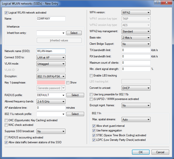
In this example, the employees of a company have access to a private WLAN (SSID), while the guests use a Public Spot to access the Internet. In all areas of the building, the APs provide two SSIDs, 'COMPANY' and 'GUESTS'.
The aim of the configuration: A WLAN client that associates with the internal SSID should have access to all internal resources and the Internet via the central gateway. The APs break-out the payload data from the internal clients locally and pass it on directly to the LAN. The guests' WLAN clients associate with the Public Spot. The APs send the payload data from the guest clients through a WLC tunnel directly to the WLC, which uses a separate WAN interface for Internet access.
-
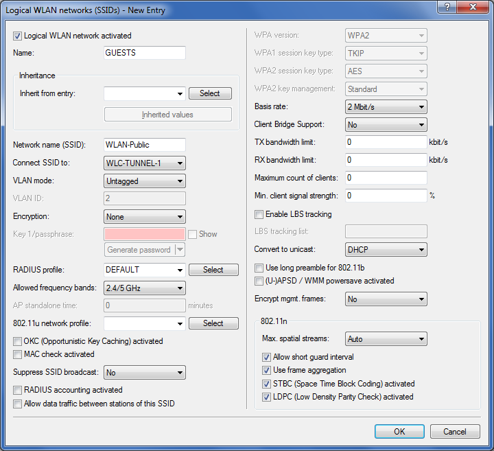
The internal WLAN and the guest WLAN each require an entry to be created in the list of logical networks, each with a suitable name and the corresponding SSID. Link the SSID for internal use with the 'LAN at AP', and the SSID for guests with (for example) 'WLC-TUNNEL-1'. Disable encryption for the guest network SSID so that the guests' WLAN clients can associate with the Public Spot. You should also prevent inter-station traffic for this SSID. In LANconfig you find this setting under .
-
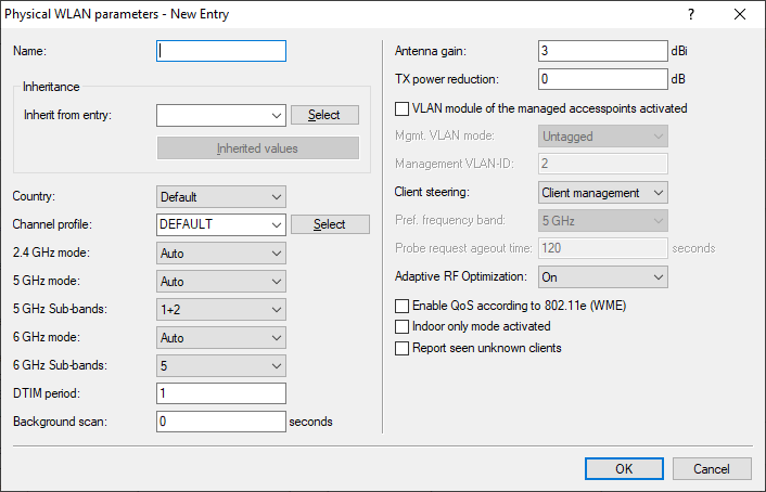
Create an entry in the list of physical WLAN parameters with the appropriate settings for your APs, such as the country 'Europe' with the channels 1, 6 and 11 in 802.11b/g/n and 802.11a/n in mixed mode. In LANconfig you find this setting under .
-
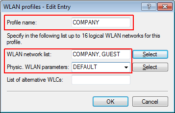
Create a WLAN profile and give it a suitable name. Then assign the logical WLAN networks and the physical WLAN parameters created previously to this WLAN profile. In LANconfig you find this setting under .
-
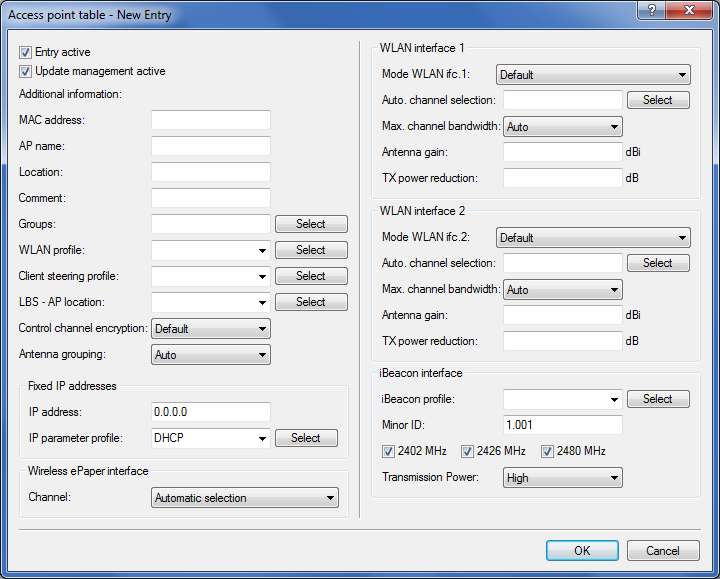
For each managed AP, create an entry in the AP table with a suitable name and the associated MAC address. Assign the previously created WLAN profile to this AP. In LANconfig you find this setting under .
-
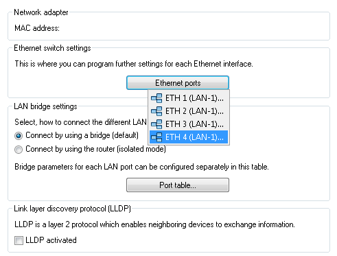
Assign a separate logical LAN interface, e.g. 'LAN-1', to each physical Ethernet port. Set the 4th Ethernet port to the logical LAN interface 'DSL-1'. The WLC then uses this LAN interface for the guest network Internet access. In LANconfig you find this setting under .
-
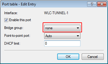
Verify that the logical LAN interface 'WLC-tunnel-1' is not allocated to a bridge group. This ensures that the other LAN interfaces do not transmit any data to the Public Spot. In LANconfig you find this setting under .
-
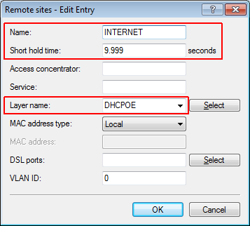
For the guest Internet access, create an entry in the list of DSL remote sites with the hold time '9999' and the pre-defined layer 'DHCPOE '. This example assumes that Internet access is provided by a router with DHCP server. In LANconfig you find this setting under .
-
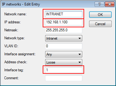
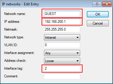
For internal users, create the IP network 'INTRANET' with (for example) the IP address '192.168.1.100' and the interface tag '1'. For the guest access, create the IP network 'GUEST-ACCESS' with (for example) the IP address of '192.168.200.1' and the interface tag '2'. The virtual router in the WLC uses the interface tags to separate the routes for the two networks. In LANconfig you find this setting under .
-
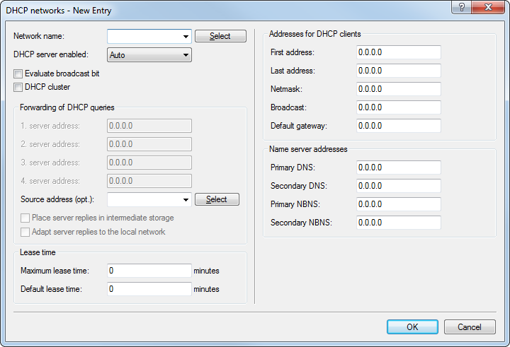
The WLC is able to act as a DHCP server for APs and the associated WLAN clients. To set this up, activate the DHCP server for the 'INTRANET' and the 'GUEST-ACCESS'. In LANconfig you find this setting under .
Note: Activation of the DHCP server is obligatory for the guest network and optional for the internal network. There are other ways of realizing a DHCP server for the internal network.
-
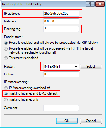
Create a new default route in the routing table to direct the data from the guest network to the Internet connection used by the WLC. Select the routing tag '2' and the router 'Internet'. Also activate the option 'Masking intranet and DMZ (default)'. In LANconfig you find this setting under .
-
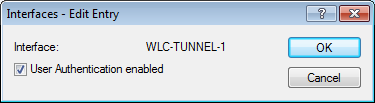
Activate the Public Spot user authentication for the logical LAN interface 'WLC-Tunnel-1'. In LANconfig you find this setting under .
-
The final step is to enable authentication via the Public Spot for the WLC. In LANconfig you find this setting under .
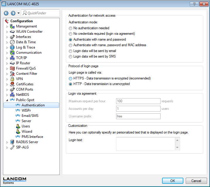
In addition to configuring the WLC, you must also configure the Public Spot either to use the internal user list or to use a RADIUS server, according to your needs.