This is an example of how L2TPv3 is used in a scenario where several access points use bridging to transfer their payload data to a central router (referred to here as the "concentrator"), where the data are made available via a separate Ethernet port.
Note: Before LCOS 10.20, this scenario would have required a WLAN controller.
- Prepare the WLAN configuration on the access points. To enable roaming, SSID names and encryption settings should be configured identically on each AP.
-
Now configure the concentrator, which is to accept the L2TPv3 Ethernet sessions from the individual access points.
-
Under in the L2TP endpoints table, create an entry "DEFAULT”. Enter a descriptive name for the new entry. Set the L2TP version to "L2TPv3". Do not specify an IP address. Set a password to increase security and enable the "Authenticate remote end" option to use the password for authentication during connection establishment. Leave the remaining settings at their default values.
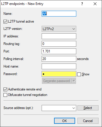
The IP address is empty. This is then a "wildcard" entry that can accept connections from any remote site.
-
Under in the L2TP Ethernet table, create a new entry. Use Remote site to set a name for the Ethernet tunnel, e.g. the name of the SSID to which the tunnel on the access points is to be linked. Leave the field L2TP endpoint empty so that any (authenticated) sessions can be accepted. This method avoids having to create an entry for each individual access point in the L2TP endpoint table: The wildcard entry created in the previous step is used instead. Under Interface you now configure the virtual interface to which the L2TP Ethernet tunnel is to be connected. If the access points operate multiple SSIDs that are to be bridged to the central site, use this table to create an entry for each SSID, each with a unique name under Remote site.
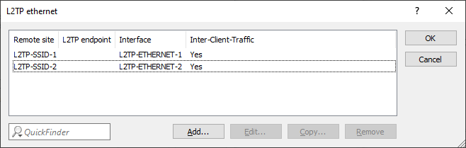
Note: In our scenario, the payload data of all connected access points are routed to the virtual interface configured here. Furthermore, the payload data of all access points connected to this virtual interface are bridged to one another—rather like the WLAN controller-based layer-3 tunneling technique. -
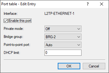
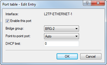
Under , link the virtual L2TP interface selected earlier to a LAN interface where you set the same bridge group. Repeat this for any additional L2TP virtual interfaces for additional SSIDs.
-
Under in the L2TP endpoints table, create an entry "DEFAULT”. Enter a descriptive name for the new entry. Set the L2TP version to "L2TPv3". Do not specify an IP address. Set a password to increase security and enable the "Authenticate remote end" option to use the password for authentication during connection establishment. Leave the remaining settings at their default values.
-
The following example shows how to configure an access point to transfer payload data to the concentrator.
-
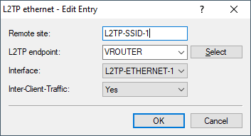
Under in the L2TP Ethernet table, create a new entry. Under Remote site, enter a name that identifies the Ethernet tunnel. This must be the same as the name given to this Ethernet tunnel on the concentrator. In the field L2TP endpoint, select the L2TP endpoint table entry that was created in the previous step. This endpoint is then used to establish the Ethernet tunnel. Under Interface you now configure the virtual interface to which the L2TP Ethernet tunnel is to be connected.
-
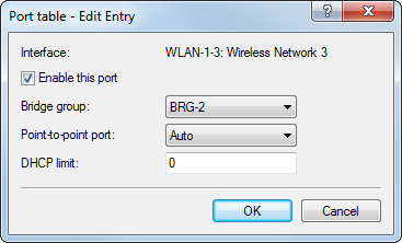
Under , link the virtual L2TP interface selected earlier to a WLAN interface by setting the same bridge group. Repeat this for any additional L2TP virtual interfaces for additional SSIDs.
-
Under in the L2TP Ethernet table, create a new entry. Under Remote site, enter a name that identifies the Ethernet tunnel. This must be the same as the name given to this Ethernet tunnel on the concentrator. In the field L2TP endpoint, select the L2TP endpoint table entry that was created in the previous step. This endpoint is then used to establish the Ethernet tunnel. Under Interface you now configure the virtual interface to which the L2TP Ethernet tunnel is to be connected.