To separate the data streams on layer 3, two different IP networks are employed (ARF – Advanced Routing and Forwarding).
-
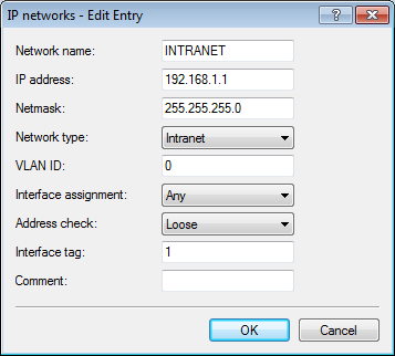
For the internal network, set the INTRANET to the address 192.168.1.1.
This IP network uses the VLAN ID 0. This assigns all untagged data packets to this network (the VLAN module in the controller itself must be activated for this). The interface tag 1 is used for the subsequent break-out of data in the virtual router.
- LANconfig:
-
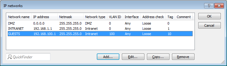
For guests, create a new IP network with the address 192.168.100.1.
This network uses the VLAN ID 100. In this way, all data packets with this ID are assigned to the guest network. Here, too, the interface tag 10 is used later by the virtual router.
- LANconfig:
-
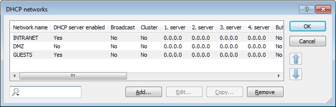
Enable the DHCP server for both IP networks.
- LANconfig:
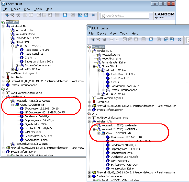
With these settings, the WLAN clients of the internal employees and guests are assigned to the appropriate networks.