A switch configuration is demonstrated with the example of a LANCOM ES-2126+.
-
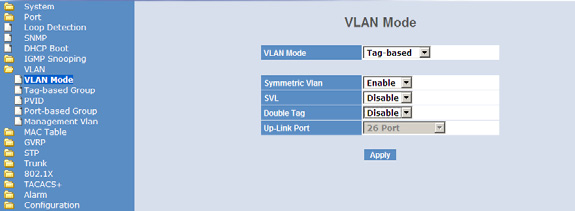
Set the VLAN mode to &Tag based&, as the access points handle the assignment of
VLAN tags.
-
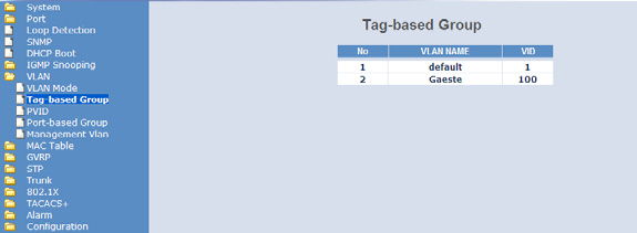
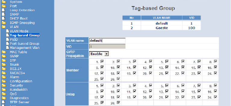
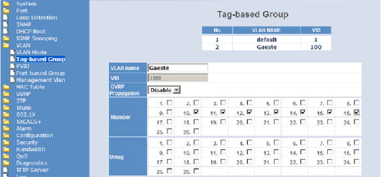
To differentiate between the VLANs in the switch, two groups are used. The internal
network for the employees is mapped to the default group, and a dedicated group is set up
for the guests. This is handled with the VLAN IDs entered into the controller when
configuring the WLANs.
-
The default VLAN is valid on all ports and remains untagged, i.e. the VLAN tags
are removed from outgoing data packets from this group.
-
The guests' VLAN group uses the VLAN ID '100' and is valid only for the
ports connected to the WLAN controller and access points (ports 10 to 16 in our example).
Tags are not removed from outgoing data packets.
-
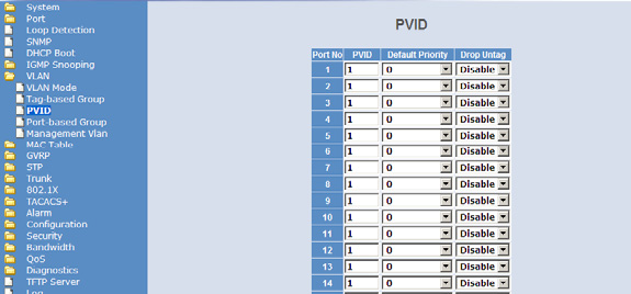
The port VLAN ID (PVID) is set to '1' for all ports, to assign the ports to
the internal network. Untagged packets arriving at these port will be forwarded with the
VLAN ID '1'.