The AP table is a central element of the configuration for WLCs. Here, the WLC assigns WLAN profiles (i.e. the combinations of logical and physical WLAN parameters) to the APs via their MAC addresses. Furthermore, the existence of an entry in the AP table for a specific AP affects its ability to connect to a WLC. Under you can define the following parameters for each AP:
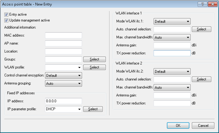
- Entry active
- Activates or deactivates this entry.
- Update management active
- Activating update management for this AP enables it to download the latest firmware and script versions automatically. All other settings are adjusted under AP update (Central firmware and script management).
- MAC address
- MAC address of the AP.
- AP name
- Name of the AP in managed mode.
- Location
- Location of the AP in managed mode.
- Groups
- Assigns the AP to one or more groups
- WLAN profile
- WLAN profile from the list of defined profiles.
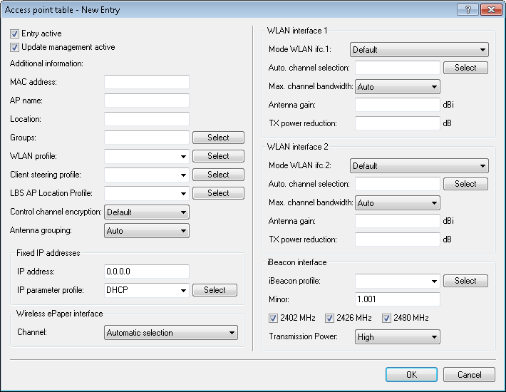
- Client steering profile
- Client-steering profiles control how the WLC decides which APs are to accept a client at the next login attempt.
- LBS AP location profile
- LBS location profile from the list of defined profiles.
- Control channel encryption
- Encryption of communications over the control channel. Without encryption, the AP and WLC exchange the control data as cleartext. In both cases authentication is by certificate.
- Antenna grouping
- Antenna grouping can be configured in order to optimize the gain from spacial multiplexing.
- IP address
- Here you specify a fixed IP address of the AP.
- IP parameter profile
- Here you specify the profile name used by the WLC to reference the IP settings for the AP. If you retain the default setting DHCP, the WLC ignores the setting for the fixed IP address and the AP is forced to obtain its IP address via DHCP.
- Channel (Wireless ePaper interface)
- Here you specify how the channel is selected for the Wireless ePaper interface.
- Mode WLAN ifc.1 1
- This setting allows you to configure the frequency band in which the AP operates the 1st physical WLAN interface. When set to Default, the AP independently selects the frequency band for the physical WLAN interface. The AP prefers the 2.4GHz band, if available.
- Mode WLAN ifc.1 2
- This setting allows you to configure the frequency band in which the AP operates the 2nd physical WLAN interface. When set to Default, the AP independently selects the frequency band for the physical WLAN interface. The AP prefers the 5GHz band, if available.
-
Note: If a managed AP only has one physical WLAN interface, the AP ignores the settings for the 2nd physical WLAN interface.
- Auto Channel selection
- If no entry is made here, APs automatically carry out the channel selection for the frequency band available in the set country of operation. Enter the channels to be available for automatic selection by the first WLAN module. If you enter just one channel here, the AP uses this channel only and no automatic selection takes place. For this reason you should ensure that the channels entered here are legal for use in the defined country of operation. The AP ignores channels that are invalid for the frequency band.
- Max. channel bandwidth
- Enter how and to what extent the AP specifies the channel bandwidth for the physical WLAN interface(s). The following values are possible:
- Automatic: The AP automatically detects the maximum channel bandwidth (default).
- 20MHz: The AP uses channels bundled at 20 MHz.
- 40MHz: The AP uses channels bundled at 40MHz.
- 80MHz: The AP uses channels bundled at 80MHz.
- 802.11n can use 52 carrier signals in a 20-MHz channel for modulation, and even up to 108 carrier signals in a 40-MHz channel. The use of the 40 MHz option for 802.11n therefore means a performance gain of more than double.
- Antenna gain
- This item allows you to specify the antenna gain factor (in dBi) minus attenuation of the cable and (if applicable) lightning protection. Based on this, as well as depending on the country where the system is operated and the frequency band, the AP calculates the maximum permitted transmission power.
If you leave the field blank, the AP uses the default setting from the configuration group in the relevant WLAN profile.
You can reduce the transmission power to a minimum of 0.5 dBm in the 2.4-GHz band or 6.5 dBm in the 5-GHz band. This limits the maximum value that can be added to 17.5 dBi in the 2.4-GHz band and 11.5 dBi in the 5-GHz band.
Important: Be sure that your combination of antenna, cable and lightning-protection complies with the legal requirements of the country where the system is operated.The receiver's sensitivity is unaffected by this.Tip: The current transmission power is displayed by WEBconfig or telnet under or with LANmonitor under .
- TX power reduction
- If you use an antenna with a high amplification factor, you can use this entry to attenuate the transmission power of your AP to the level permitted on the frequency band in the country of operation. If you leave the field blank, the AP uses the default setting from the configuration group in the relevant WLAN profile. The same values and constraints apply as for the field Antenna gain.
- iBeacon profile (iBeacon interface)
- Select an iBeacon profile from the list of profiles created.
-
Note: You create iBeacon profiles under .
- Minor
- Set a minor ID for the iBeacon module.
- 2402 MHz, 2426 MHz, 2480 MHz
- Specify here which channels the iBeacon module uses to transmit.
- Transmission power
- Specify the power used by the iBeacon module to transmit. The following values are possible:
- High: The module sends with maximum power (default).
- Medium: The module sends with medium power.
- Low: The module sends with minimum power.