In many cases, networks in a shared physical infrastructure are separated by using VLANs. However, this method assumes that the switches operated in the network are VLAN-capable and that these are configured for VLAN operations. Consequently, the administrator has to rollout the VLAN configuration for the whole network.
WLCs enable you to keep networks separate while minimizing the use of VLANs. The APs use a CAPWAP data tunnel to direct the payload from the WLAN clients straight to the WLC, which then assigns the data to the corresponding VLANs. In this situation, VLAN configuration is only required for the WLC and a single, central switch. All of the other switches in this example work without a VLAN configuration.
The diagram shows a sample application with the following components:
- The network consists of two segments, each with its own (not necessarily VLAN-capable) switch.
- Each segment contains several APs, each of which is connected to one of the switches.
- Each AP provides two SSIDs for the WLAN clients in two different user groups, shown in the diagram in green and orange.
- Each user group has access to its own dedicated server that is separated from other user group. The servers can only be accessed via the corresponding VLANs, i.e. through the access ports configured on the switch.
- A WLC manages all APs in the network.
- A central, VLAN-capable switch connects the switches in each segment, the servers for each group, and the WLC.
The aim of the configuration: A WLAN client that associates with an SSID is to have access to its "own" server, regardless of which AP is being used and regardless of the segment in which the client is located.
Configuring the WLAN settings
-
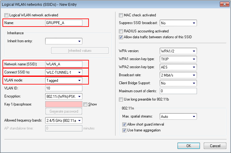
For each SSID, create an entry in the list of logical networks. This entry requires a suitable name and the corresponding SSID. Connect the SSID to a WLC tunnel, for example the first SSID to "WLC-TUNNEL-1" and the second to "WLC-TUNNEL-2 '. Set the VLAN mode to 'tagged', set the VLAN ID '10' for the first logical network and the VLAN ID '20' for the second logical network. In LANconfig you find these settings under .
-
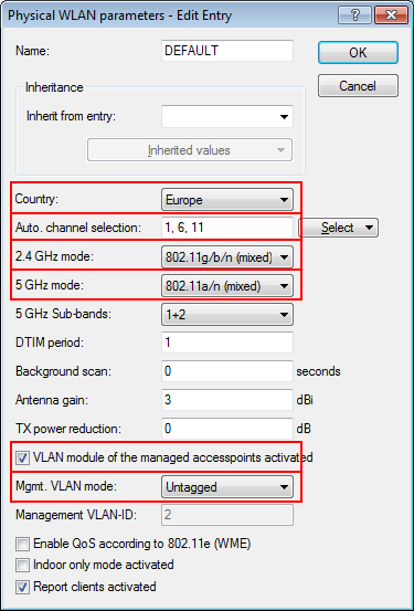
Create an entry in the list of physical WLAN parameters with the appropriate settings for your APs, such as the country 'Europe' with the channels 1, 6 and 11 in 802.11b/g/n and 802.11a/n in mixed mode. For this profile in the physical WLAN parameters, enable the option to turn on the VLAN module on the APs. Set the operating mode for the management VLAN in the AP to 'Untagged'. In LANconfig you find these settings under .
-
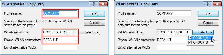
Create a WLAN profile and give it a suitable name. Then assign the logical WLAN networks and the physical WLAN parameters created previously to this WLAN profile. In LANconfig you find these settings under .
-
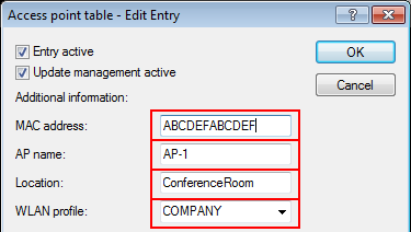
For each managed AP, create an entry in the AP table with a suitable name and the associated MAC address. Assign the WLAN profile created previously to this AP. In LANconfig you find these settings under .
Configuring the interfaces on the WLC
-
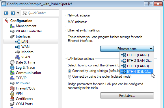
Assign a separate logical LAN interface, e.g. 'LAN-1', to each physical Ethernet port. Make sure that the other Ethernet ports are not assigned to the same LAN interface. In LANconfig you find these settings under .
-
Assign the logical LAN interface 'LAN-1' and the WLC tunnels 'WLC-tunnel-1' and 'WLC-tunnel-2' to the bridge-group 'BRG-1'. Make sure that the other LAN ports are not assigned to the same bridge group. In LANconfig you find these settings under .
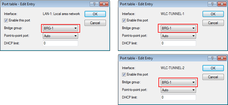 Note: By default, the LAN interfaces and WLC tunnels do not belong to a bridge group. By assigning the LAN interface 'LAN-1' and the two WLC tunnels 'WLC-Tunnel-1' and 'WLC-Tunnel-2' to the bridge group 'BRG-1', the device transmits all data packets between LAN-1 and the WLC tunnels via the bridge.
 -
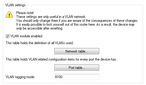
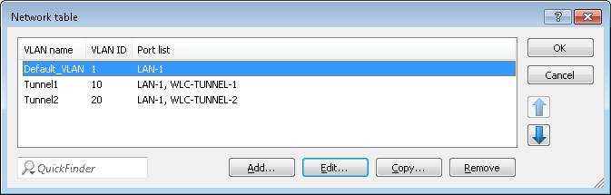
Under , activate the VLAN module of the WLC and, under VLAN table, assign the LAN port you selected above (LAN 1) together with the matching WLC tunnel to the desired VLAN.
-
Under , enter the Tagging mode of the tunnel interface and the LAN interface, and set the appropriate port VLAN ID.
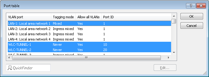
Depending on how the switch is configured, set the Tagging mode of the LAN interface to 'Mixed' or 'Always'.
In most cases it is desirable to operate the tunnel interfaces with the mode 'Never', because packets here (from the WLAN) always arrive untagged and the WLC marks them with the port VLAN ID
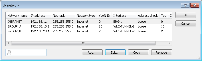
Important: When you activate the VLAN module, please observe that the ARF networks configured on the WLC must be given a VLAN ID. If the WLC is to reach the network without a VLAN tag, then for the VLAN configuration used above the VLAN-ID for the IP network must be set to '1'.Note:A similar configuration can be achieved if you use the access point to set a VLAN tag for packets that are intended to be sent via the tunnel instead of using the VLAN module of the WLC.
However, this bridging between the various WLC tunnels causes the WLC to redirect broadcasts into all of the tunnels; with a certain number of tunnels/SSIDs and APs, this can lead to load problems on the network and on the WLC. This configuration of VLAN module prevents this.
-
Under you additionally configure the IP settings for the networks separated on layer 2.
Important: To prevent the device connecting these networks on layer 3, the separation needs to be configured on this layer too, for example by using a port tag or by means of the firewall.
-
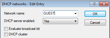
The WLC can optionally act as a DHCP server for the APs. To set this up, activate the DHCP server for the 'INTRANET'. In LANconfig you find these settings under .