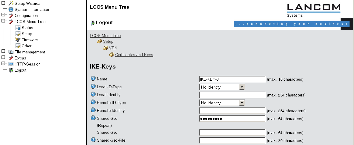
- Under Configuration / VPN / IKE-Param. / IKE key set a new IKE key for the connection:
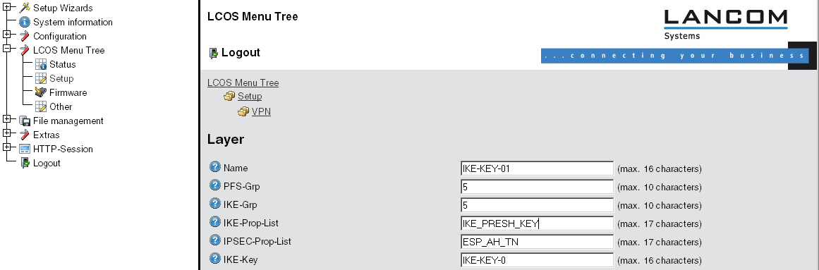
- Under Configuration / VPN / General / Connection parameters define a new “VPN layer” for the connection parameters. Select the IKE key created earlier for this.
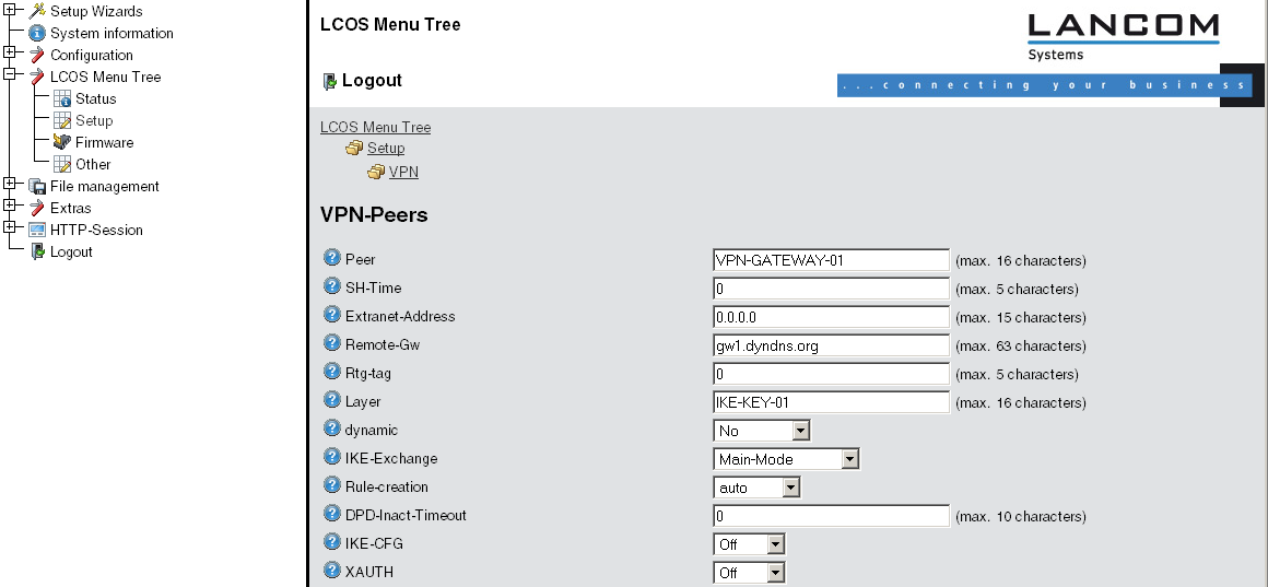
- Under Configuration / VPN / Connection list generate a new entry with the name of the remote gateway set to “Name”. For the “Remote gateway”, enter the public address of the remote station: either the fixed IP address or the name for translation by DNS.
- When using LANCOM Dynamic VPN: Under Configuration / Setup / WAN module / PPP list make a new entry. Select the remote VPN gateway as the remote site, enter the User Name as the name of the VPN connection that the remote VPN gateway uses to address the local device, and enter a suitable password that is identical at both locations.
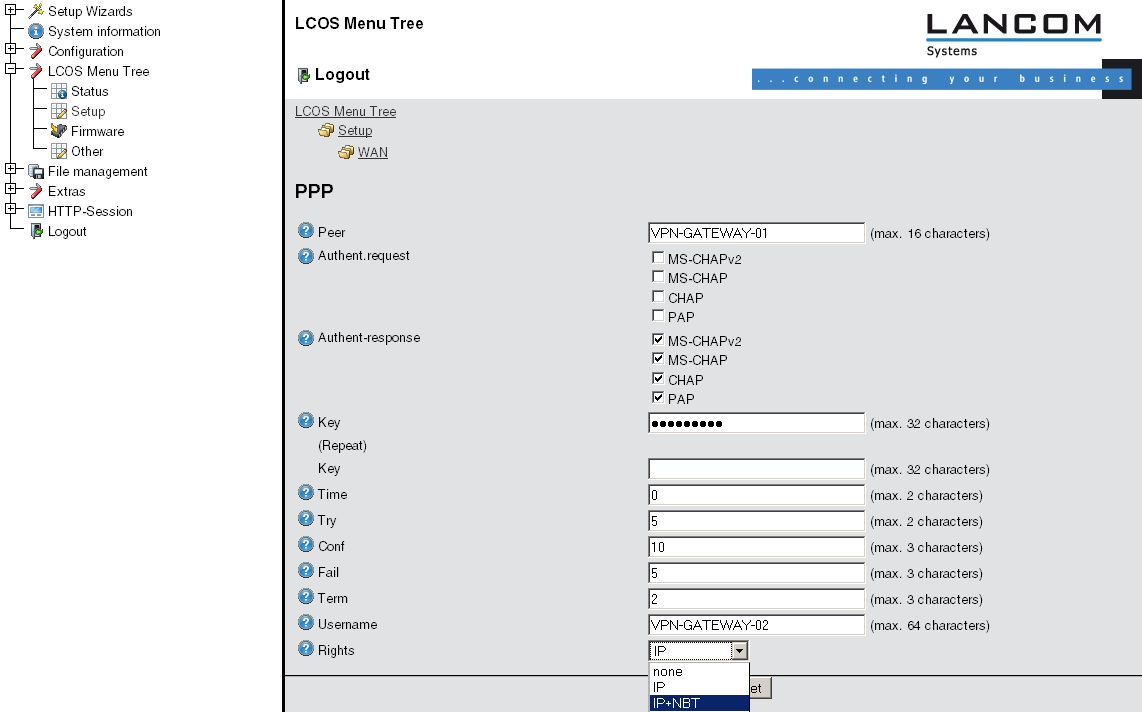
- Be sure to activate "IP routing" and, if required, "NetBIOS over IP".
- Under Configuration / Setup / IP router module / IP routing table generate a new entry for each network portion that should be accessible in the remote and in the local LAN. In each case, define the router as the remote VPN gateway and switch the IP masquerading off.
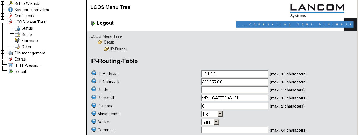
- For the “VPN gateway 2”, the following entries are necessary so that the
remote network sections can be reached.
For those subnetworks connected to your own LAN, define the router as the IP address for the appropriate LAN router.
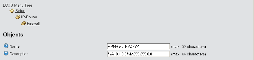
IP address Net mask Router IP masquerading 10.1.0.0 255.255.0.0 VPN gateway 1 No 10.2.0.0 255.255.0.0 VPN gateway 1 No 10.3.0.0 255.255.0.0 VPN gateway 1 No These entries enable VPN gateway 2 to forward packets arriving from the remote network to the correct sections of the local network.IP address Net mask Router IP masquerading 10.5.0.0 255.255.0.0 10.4.00.5 No - Under Configuration / Firewall/QoS / Object table make an entry for each part of the network that should be used as a source or destination for the VPN connection via “VPN GATEWAY 1” (“VPN-GW1-LOCAL” and “VPN-GW1-REMOTE”). Enter each subnet in the form “%A10.1.0.0 %M255.255.0.0”.
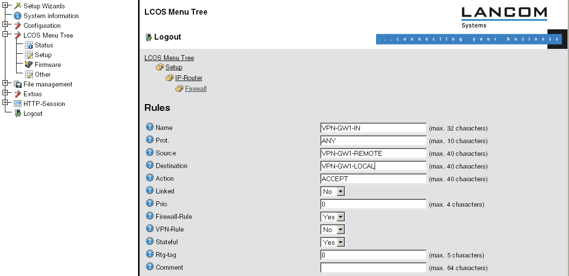
- Under Configuration / Firewall/QoS / Rules table define a new firewall rule named “VPN-GW1-OUT”. Set the objects to “CPN-GW1-LOCAL” and “VPN-GW1-REMOTE”, the protocol to “ANY” and the action to “ACCEPT”. Activate the option “VPN rule” so that the IP networks described in this rule will be used in establishing VPN network relationships.

Note: As a rule, it is recommended that you keep the rules used for making network relationships
separate from those firewall rules that affect the services used in communications, for
example.
- Now for the incoming data transmissions, generate a firewall rule named “VPN-GWY1-IN” with the same parameters as the rule just described. The only difference is that the source and the destination networks are swapped.