The section demonstrates how LANconfig can be used to configure a LAN-LAN coupling with additional subnets. In this section, VPN gateway 1 will be configured and then the configuration of gateway 2 with the help of WEBconfig will be demonstrated.
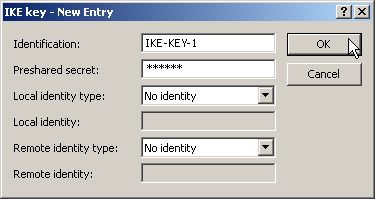
- When configuring VPN, access the “IKE param.” tab and create a new IKE key for the connection:
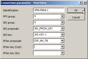
- Under the “General” tab, create a new entry in the list of Connection parameters. Select the IKE key created earlier for this. PFS and IKE groups can also be selected in the same way as IKE and IPSec proposals from the options prepared earlier.
- You should then generate a new entry in the Connection list with the name of the remote gateway as “name for the connection”. For LANCOM Dynamic VPN connections the entry “Remote gateway” must remain empty. Otherwise enter the public address of the remote station: either the fixed IP address or the name for translation by DNS.

- When using LANCOM Dynamic VPN: Change to the “Communication” configuration area. Using the “Protocols” tab, make a new entry in the PPP list. Select the remote VPN gateway as the remote site, enter the User Name as the name of the VPN connection that the remote VPN gateway uses to address the local device, and enter a suitable password that is identical at both locations, but for safety reasons should not be identical to the pre-shared key.
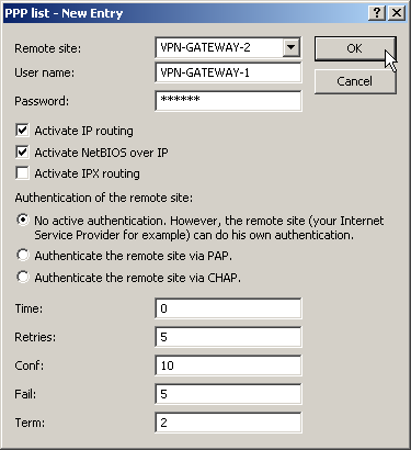
- Be sure to activate "IP routing" and, if required, "NetBIOS over IP".
- Change to the “IP Router” configuration area. On the “Routing” tab, make a new entry in the routing table for those parts of networks that are to be accessible in the remote and in the local LAN. In each case, define the router as the remote VPN gateway and switch the IP masquerading off.
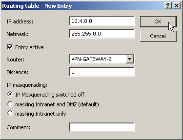
- For the “VPN gateway 1”, the following entries are necessary so
that the remote network sections can be reached.
For those subnetworks connected to your own LAN, define the router as the IP address for the appropriate LAN router.
IP address Net mask Router IP masquerading 10.4.00.0 255.255.0.0 VPN gateway 2 No 10.5.0.0 255.255.0.0 VPN gateway 2 No These entries enable VPN gateway 1 to forward packets arriving from the remote network to the correct sections of the local network.IP address Net mask Router IP masquerading 10.2.0.0 255.255.0.0 10.1.0.2 No 10.3.0.0 255.255.0.0 10.1.0.3 No - Change to the “Firewall/QoS” configuration area. On the “Rules” tab, add a new firewall rule with the name “VPN GATEWAY 1 OUT” and activate the option “This rule is used to create VPN rules”. This ensures that IP networks described in this rule will be used in establishing VPN network relationships.
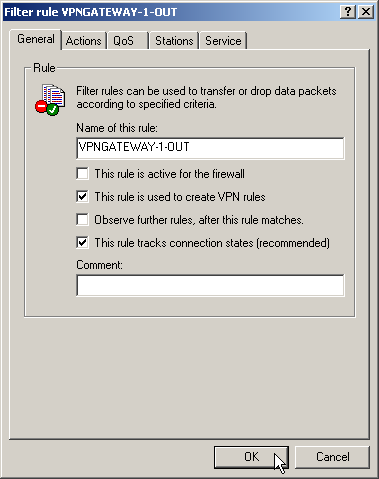
Note: It is recommended to keep the rules
used for making network relationships (source and target IP) separate
from those firewall rules that for instance affect the services used
in communications. Combining both aspects can leed to a higher number
of internal managed VPN relationships and therefore to a loss of performance
in the VPN tunnels.
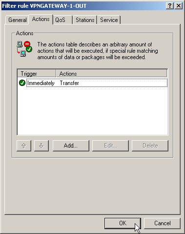
- On the “Actions” tab for these firewall rules, set the “Packet Action” to “Transmit”.
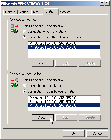
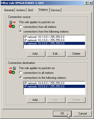
- On the “Stations” tab for these firewall rules, define the source of the data transfers as the subnets at the local site, and set the destination as all of the subnets at the remote site.
- Now for the incoming data transmissions, generate a firewall rule named “VPN GATEWAY 1 IN” with the same parameters as the rule just described. The only difference is that the source and the destination networks are swapped.