Configuring WWAN access

The following tutorial shows how you manually configure devices with an internal cellular modem to use access via mobile networks (WWAN). First you either create a mobile profile for your provider or edit an existing profile, and then you assign this profile to the WAN interface of the device.

Alternatively, a simpler and faster way of configuration is available with a Setup Wizard (Set up Internet access).

  1. In LANconfig, open the configuration dialog for your device and navigate to the section Interfaces > WAN.
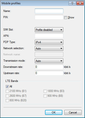
  2. Select an existing profile to be edited or add a new profile for your provider in the Mobile profiles table.

    In the interests of completeness this tutorial explains the creation of a new profile.


  3. Under Name type in a unique label for the mobile profile.
  4. Under PIN enter the 4-digit PIN of the mobile phone SIM card. The device needs this information to operate the mobile modem.
    Important: The SIM card logs every failed attempt with an incorrect PIN. The number of failed attempts remains stored even when the device is temporarily disconnected from the mains. After 3 failed attempts, the SIM card is locked from further access attempts. If this occurs, you usually need the 8-digit PUK or SuperPIN to unlock it.
  5. If your device accommodates several SIM cards, use SIM slot to select the SIM card that you want to associate with this profile.

    The item Profile disabled switches this mobile profile off. This option is useful if you wish to create a profile template only and complete the mobile setup at a later time.

    Note: Only enabled profiles are visible for selection in LANmonitor.
  6. Under APN, enter the name of the access server for the data services of your mobile provider.
    The APN (access point name) is specific to each mobile phone provider. You will usually find this information in the documentation provided with your mobile phone contract.
  7. Under PDP type you specify the type of the PDP context for the mobile profile.
    The PDP context describes the support of the address spaces which the backbone of the corresponding cellular network provider offers for connections from the cellular network to the Internet. This can be either IPv4 or IPv6 alone, or can include support for both address spaces (dual stack). Clients that want to use the corresponding cellular network provider must support at least one of the specified address spaces.
  8. Set the preferred Network selection mode:
    Automatic
    The mobile modem automatically connects to one of the available and permitted mobile phone networks.
    Manual
    The mobile modem connects to the specified mobile phone network only.
    Note: Manual mobile network selection is especially suitable when the device is in stationary operation and you wish to prevent it from connecting to another undesirable or more expensive mobile phone network.
  9. If you have selected manual network selection, enter the exact name of your desired network under Network name.
  10. Specify the preferred transfer mode within the mobile network under Transmission mode:
    Automatic
    Automatic selection of transmission mode
    LTE
    LTE/4G mode only
    UMTS + GPRS
    Combined UMTS/3G & GPRS mode
    UMTS
    UMTS/3G mode only
    GPRS
    GPRS mode only
  11. Under Downstream rate and Upstream rate you specify the transfer rates for the mobile phone connection. This is important for the QoS (quality-of-service) feature and the functioning of the firewall.
    If the value is set to 0, the mobile interface in the corresponding direction is considered to be unlimited and the QoS mechanisms will not take effect.
  12. If unfavorable environmental conditions cause the router to constantly switch between two frequency bands, instabilities in the transmission may be the result. The selection under LTE bands allows you to control which frequency bands are used by the mobile modem.
    All
    All frequency bands are enabled.
    2100 MHz (B1)
    2.1GHz band is enabled.
    1800 MHz (B3)
    1.8GHz band is enabled.
    2600 MHz (B7)
    2.6GHz band is enabled.
    900 MHz (B8)
    900MHz band is enabled.
    800 MHz (B20)
    800MHz band is enabled.
    Note: This option applies only to the LTE standard frequency bands. All bands can be used for UMTS and GPRS.
  13. Click OK to save the settings.
  14. In the dialog Interfaces > WAN, click Interface settings and select V.24/Mobile.
  15. Set the V.24/Mobile interface to Mobile.
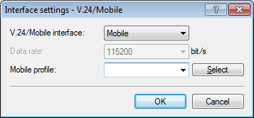
  16. Under Mobile profiles, select the profile you created earlier for your mobile phone provider.
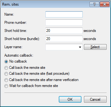


  17. Click OK to save the settings.
  18. In the view Communication > Remote sites, click Rem. (Mobile /...) and add a new profile.


  19. Enter a unique name for the profile under Name, e.g. WWAN.
  20. Under Phone number, enter the dial-in number of your mobile phone provider. If your provider has not given you a dial-in phone number, enter *99#.
  21. Under Short hold time, enter the time after which the device disconnects from the remote site if no packets are transmitted

    Enter a value in seconds to find a balance between the costs arising from idle time those of connection establishment, for example 300. A value of 0 causes the device to stay connected until it is broken and terminated. With a value of 9999 the device automatically reconnects every time.

  22. For Layer name select the presetting UMTS.
  23. Click OK to save the settings.
  24. In the view Communication > Protocols, open the PPP list and add a new remote site.


  25. Under Remote site, select the profile that you created previously, e.g. WWAN.
  26. Deselect any settings under Authentication of the remote site (request).
  27. Click OK to save the settings.
  28. In the view IP Router > Routing, click IPv4 routing table and add the Default route (255.255.255.255).


  29. Under Router, select the profile created earlier under Rem. sites (Mobile /...).
  30. Set the IP masquerading to Masking intranet and DMZ (default).
  31. Click OK to save the settings.
  32. Write the changes back to the device.
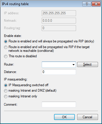
This concludes the configuration of the WWLAN access.